
drpops
Member
Guys,
I have a couple of non-functional mr4 meters. Having studied the circuit diagram and with nothing to loose.
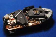
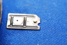
I began my exploratory surgery. I have included some pics of the patient along the way.
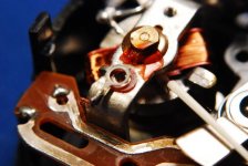
I now know more about the intricacies of the Leica meter than I thought possible. The galvanometer that moves the needle is a very delicate with gorgeous minute watch springs to move the needle to the rest position.
With the exception of the galvanometer, this is a very robust design. It can be recalibrated to use 1.5 silver oxide cells.....but you then need to surgically change the 2 resistors that are in the battery check loop.
I would really love to change to a bar graph output that would indicate exposure.....that galvanometer is just too fussy.
I will keep you guys abreast of my progress.
David
I have a couple of non-functional mr4 meters. Having studied the circuit diagram and with nothing to loose.
I began my exploratory surgery. I have included some pics of the patient along the way.
I now know more about the intricacies of the Leica meter than I thought possible. The galvanometer that moves the needle is a very delicate with gorgeous minute watch springs to move the needle to the rest position.
With the exception of the galvanometer, this is a very robust design. It can be recalibrated to use 1.5 silver oxide cells.....but you then need to surgically change the 2 resistors that are in the battery check loop.
I would really love to change to a bar graph output that would indicate exposure.....that galvanometer is just too fussy.
I will keep you guys abreast of my progress.
David
Attachments
robklurfield
eclipse
you are brave. of course, you did say, nothing to lose. let us know your patient's progress.
t.s.k.
Hooked on philm
....or your patience ")
Beemermark
Mentor
I used to repair these a long time ago. I do not remember the particulars but generally the problem was dirt on the contacts or galvanometer. Gentle cleaning with Radio Shack Contact cleaner usually restored them to life. The circuit has a Rosetta bridge which automatically compensated for the changing voltage in a silver oxide battery. Often they do not even need to be re-calibrated. Newer MR-4 meters show that either the PX-625 (silver oxide) or PX-13 (mercury) can be used. I think they are the best meters available for the M series with out a meter.
drpops
Member
Well....as a great engineer once told me...they didn't work this morning....the worst that can happen is that they don't work tonight either. I also asked the patient if I could do the surgery and no complaint was lodged, so away I went.
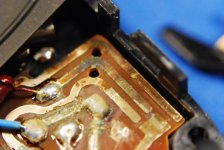
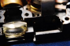
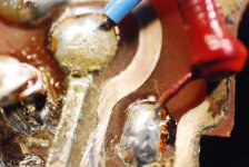
But now I have measured data for the resistor ranges , those that are adjustable, the resistor values for those that are fixed. I also have the resistance value for the Cds cells when exposed to a wide bandwidth of lighting and intensity. The 2 Cds cells read nearly the same value with surprising consistency. I had frequently been told these cells fail when they get old. From my exploration I cannot confirm this parable.
Having this data and measured values, I can now calculate the expected current to be fed to the galvanometer. This now gives me the values should I wish to look for a substitute output metering system. i.e. digital bar graph in the window.
And yes my patience has reached a new height.
thanks for the input,
Dave
Attachments
Last edited:
jamato8
Corroding tank M9 35 ASPH
I still have some mercury NOS for my meter. The one I have in the meter still works after 25 years, which I find hard to believe but it does. I keep the batteries about 6 in the frig. I don't know when I will ever use them.
dof
Fiat Lux
As a confirmed geek fanboy I have to say, "This thread is dope."
Please, please continue...
Back to your regularly scheduled doldrums
Please, please continue...
Back to your regularly scheduled doldrums
drpops
Member
Well, now I have a great electrical schematic for the meter along with the values and ranges for the resistors, Cds cell and galvanometer. Now I know too much...the galvanometer is THE weak link in the system. I would really love to replace it with a simple Integrated chip with digital display.
Share: