
wolves3012
Mentor
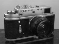
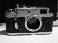
Zorki 4K "HOW TO - CLA" here. hope you like it!
NOTE 1 - most photos will be in the posts below the sections - there are more than 5
photos in most sections!
NOTE 2: You can use this for a Zorki 4 as well. Apart from the winder, the two models are identical. To remove the winder knob on the Zorki 4, slacken the small grub-screw in it and then unscrew it. Ignore the parts about the rewind lever and its associated gears thereafter.
NOTE 3: towards the end of the posts there's a link from Vido, who kindly turned this into a PDF file for download.
Attachments
Last edited:
wolves3012
Mentor
General Precautions, Warnings etc
Firstly, on your own head be it! I accept no responsibility if you decide to take your
camera apart and damage something or can't put it back together. If you are in doubt
about your ability to cope with the work needed, leave it to a professional. You will need
time to complete this task, together with the right tools and somewhere to work and possibly
to leave a part-assembled camera. Good lighting is essential, as is either good eyesight or
the neccessary vision aids! There are many small parts, such as screws, which are easily
lost. Have a sheet of white paper to work on, at least A4 size and preferably A3. Dropped
screws are easier to see on white paper than newspaper, though a larger layer of newspaper
underneath provides a secondary catchment and some absorbency for any spills.
I suggest you read the whole article before you start, that way you'll see what's needed and
what's involved before you bite the bullet. If you intend to leave the job partway, I suggest
putting screws back into their holes partway. They are less likely to become lost and you
won't have to remember which screw goes where.
Don't use brute force to undo any part - if it's very tight, find out why first. If corrosion
is the cause, try some penetrating oil and gentle heat. Leave the parts to soak with penetrating
oil. Remember too that some threads are left-handed, meaning that you need to turn clockwise
to loosen them. I've noted left-hand threads in the text.
Have regard for your personal safety. Use cleaning fluids only in well-ventilated places
and be aware that many of them are highly flammable. Keep liquids away from your work area
except when needed - it's very easy to spill oil all over your nice cleaned work!
It's good practice to keep "wet" and "dry" work in separate areas, taking only the parts
needed into the "wet" area.
Left/Right/Front/Back
Any references I've made to these assume that you're holding the camera in front of you as
if about to take a photo, with the lens away from you.
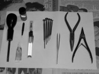
Tools (photo 1)
You'll need the following:
Large screwdriver with a flat blade of around 8-10mm.
Set of small screwdrivers with blades from about 1mm to 2.5mm wide.
A sewing needle or drill-bit of about 1-1.2mm diameter.
Pair of needle-nose or circlip pliers - they need to have fairly sharply pointed tips.
Tweezers - preferably jewellers type.
Precision oiler - a hypodermic & syringe (not too sharp!) is a good alternative.
Oiler - a needle or thin wire can also be used.
Thin oil - watch oil is preferable, "3-in-1 oil", "plus-gas" or similar is ok.
Medium grade oil - something regarded as a thin motor-oil would be suitable, silicone
is better still since it doesn't age much.
Grease - ideally silicone-based but thinner motor-grease could be ok.
Cleaning fluid - Lighter-petrol or, preferably, a proper watch/clock cleaning fluid.
A small paintbrush or similar to work cleaning fluid into parts.
Small containers to put fluids in and to store parts in.
Firstly, on your own head be it! I accept no responsibility if you decide to take your
camera apart and damage something or can't put it back together. If you are in doubt
about your ability to cope with the work needed, leave it to a professional. You will need
time to complete this task, together with the right tools and somewhere to work and possibly
to leave a part-assembled camera. Good lighting is essential, as is either good eyesight or
the neccessary vision aids! There are many small parts, such as screws, which are easily
lost. Have a sheet of white paper to work on, at least A4 size and preferably A3. Dropped
screws are easier to see on white paper than newspaper, though a larger layer of newspaper
underneath provides a secondary catchment and some absorbency for any spills.
I suggest you read the whole article before you start, that way you'll see what's needed and
what's involved before you bite the bullet. If you intend to leave the job partway, I suggest
putting screws back into their holes partway. They are less likely to become lost and you
won't have to remember which screw goes where.
Don't use brute force to undo any part - if it's very tight, find out why first. If corrosion
is the cause, try some penetrating oil and gentle heat. Leave the parts to soak with penetrating
oil. Remember too that some threads are left-handed, meaning that you need to turn clockwise
to loosen them. I've noted left-hand threads in the text.
Have regard for your personal safety. Use cleaning fluids only in well-ventilated places
and be aware that many of them are highly flammable. Keep liquids away from your work area
except when needed - it's very easy to spill oil all over your nice cleaned work!
It's good practice to keep "wet" and "dry" work in separate areas, taking only the parts
needed into the "wet" area.
Left/Right/Front/Back
Any references I've made to these assume that you're holding the camera in front of you as
if about to take a photo, with the lens away from you.
Tools (photo 1)
You'll need the following:
Large screwdriver with a flat blade of around 8-10mm.
Set of small screwdrivers with blades from about 1mm to 2.5mm wide.
A sewing needle or drill-bit of about 1-1.2mm diameter.
Pair of needle-nose or circlip pliers - they need to have fairly sharply pointed tips.
Tweezers - preferably jewellers type.
Precision oiler - a hypodermic & syringe (not too sharp!) is a good alternative.
Oiler - a needle or thin wire can also be used.
Thin oil - watch oil is preferable, "3-in-1 oil", "plus-gas" or similar is ok.
Medium grade oil - something regarded as a thin motor-oil would be suitable, silicone
is better still since it doesn't age much.
Grease - ideally silicone-based but thinner motor-grease could be ok.
Cleaning fluid - Lighter-petrol or, preferably, a proper watch/clock cleaning fluid.
A small paintbrush or similar to work cleaning fluid into parts.
Small containers to put fluids in and to store parts in.
Attachments
Last edited:
wolves3012
Mentor
Part One - Top Cover Removal
This part covers removing the top cover, with some notes on re-assembly afterwards.
Firstly, take the lens off and put it away somewhere, you won't need it for a while!
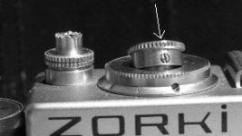
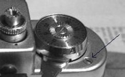
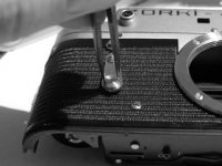
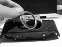
Slacken the two grub-screws on the rim of the shutter dial (photo 2). Don't remove them, just
undo them enough to allow the dial to lift off. This is easier if the shutter is cocked
and the speed set to about 1/2 sec. Trip the shutter afterwards though. While you're
near there, slacken the grub screw on the synchro ring too, setting the ring to "X" first
(photo 2 shows the screw clearly, below the arrowed one).
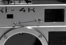
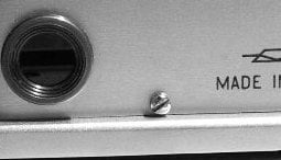
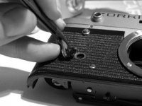
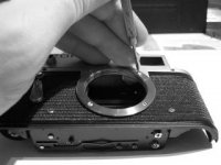
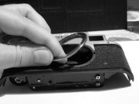
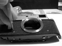
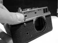
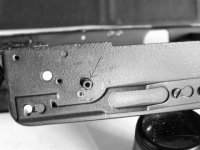
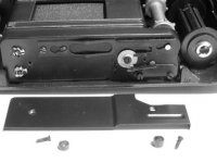
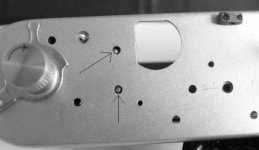
From the top-plate, remove the two front screws (photo 3), one rear screw (photo 4), one screw
from the accessory shoe (photo 5) and 1 screw near the wind-lever (photo 6). These are all
different so make sure you know where they belong!
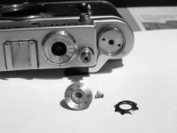
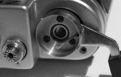
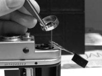
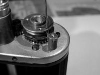
Remove the screw from the middle of the frame counter and remove the counter, together
with the star washer underneath. Underneath you will find a disc with two holes.(photo 7)
Remove the camera back and use a large screwdriver in the bottom of the spool to keep it still.
Now, whilst holding the screwdriver, undo the disc on top with the needle-nose pliers or
circlip pliers - you need 3 hands for this really! (photo 8) NOTE: LEFT-HAND THREAD so turn
CLOCKWISE. You can take a shortcut here by winding the shutter first then not using the large
screwdriver, since the mechanism will hold it. However, this puts quite a strain on various
gears and isn't wise unless the drum comes undone without much force. Remove the drum, the film
spool will fall out now or can be removed easily.
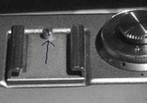
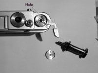
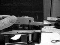
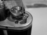
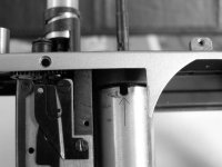
Under the disc are three screws - DO NOT remove them yet! Look next to the wind lever and you
will see a small hole (photo 9) by the three screws. Wind the lever until this hole passes the
screw hole on the top plate and hold it there (photo 9 shows the correct position). The lever
will be roughly at 90 degrees to the body at this point. Insert a needle or drill bit into the
hole as far as possible but using no force (photos 10 & 11). Release the wind-lever, it should
not return far from its current position. If the lever returns normally, you did not wind
far enough before inserting the pin, so go back and try again. You may have to release the
shutter first.
Once the pin is correctly in place, undo the three screws holding the drum and lever in place.
Lift the drum and lever, carefully, over the pin (photo 12).
Now lift the top cover off (photo 13). It should not require any force. Lift the outer end
of the wind-lever spring off the post (photos 14 & 15 and lift the spring and bobbin assembly
off as one. Take great care not to disturb the pin, if it comes out the spring WILL FLY and it
has rather sharp edges! You have been warned! You will also have to wind the spring back onto
its bobbin, which is tedious and fiddly. Set the assembly aside somewhere it won't get
disturbed.
Make sure the shutter is released, then note the position of the ramps on the ratchet
gear underneath, relative to where it meshes (photo 16), then lift the gear off its pivot.
That's the top cover removed. Next we move on to the bits exposed!
This part covers removing the top cover, with some notes on re-assembly afterwards.
Firstly, take the lens off and put it away somewhere, you won't need it for a while!
Slacken the two grub-screws on the rim of the shutter dial (photo 2). Don't remove them, just
undo them enough to allow the dial to lift off. This is easier if the shutter is cocked
and the speed set to about 1/2 sec. Trip the shutter afterwards though. While you're
near there, slacken the grub screw on the synchro ring too, setting the ring to "X" first
(photo 2 shows the screw clearly, below the arrowed one).
From the top-plate, remove the two front screws (photo 3), one rear screw (photo 4), one screw
from the accessory shoe (photo 5) and 1 screw near the wind-lever (photo 6). These are all
different so make sure you know where they belong!
Remove the screw from the middle of the frame counter and remove the counter, together
with the star washer underneath. Underneath you will find a disc with two holes.(photo 7)
Remove the camera back and use a large screwdriver in the bottom of the spool to keep it still.
Now, whilst holding the screwdriver, undo the disc on top with the needle-nose pliers or
circlip pliers - you need 3 hands for this really! (photo 8) NOTE: LEFT-HAND THREAD so turn
CLOCKWISE. You can take a shortcut here by winding the shutter first then not using the large
screwdriver, since the mechanism will hold it. However, this puts quite a strain on various
gears and isn't wise unless the drum comes undone without much force. Remove the drum, the film
spool will fall out now or can be removed easily.
Under the disc are three screws - DO NOT remove them yet! Look next to the wind lever and you
will see a small hole (photo 9) by the three screws. Wind the lever until this hole passes the
screw hole on the top plate and hold it there (photo 9 shows the correct position). The lever
will be roughly at 90 degrees to the body at this point. Insert a needle or drill bit into the
hole as far as possible but using no force (photos 10 & 11). Release the wind-lever, it should
not return far from its current position. If the lever returns normally, you did not wind
far enough before inserting the pin, so go back and try again. You may have to release the
shutter first.
Once the pin is correctly in place, undo the three screws holding the drum and lever in place.
Lift the drum and lever, carefully, over the pin (photo 12).
Now lift the top cover off (photo 13). It should not require any force. Lift the outer end
of the wind-lever spring off the post (photos 14 & 15 and lift the spring and bobbin assembly
off as one. Take great care not to disturb the pin, if it comes out the spring WILL FLY and it
has rather sharp edges! You have been warned! You will also have to wind the spring back onto
its bobbin, which is tedious and fiddly. Set the assembly aside somewhere it won't get
disturbed.
Make sure the shutter is released, then note the position of the ramps on the ratchet
gear underneath, relative to where it meshes (photo 16), then lift the gear off its pivot.
That's the top cover removed. Next we move on to the bits exposed!
wolves3012
Mentor
wolves3012
Mentor
wolves3012
Mentor
wolves3012
Mentor
Part 2
This part covers removing and servicing the slow-speed mechanism and assumes the top cover
is off.
The mechanism sits over the speed-change mechanism and under the flash-synch switch (photo 17).
The switch is held in place by two screws on diagonal corners. Don't be fooled by the third
foot and hole - no screw there! Lift off the flash-synch switch carefully. While it's off,
clean the contact ring (photo 18) with a fibreglass or fine brass brush if you have one, otherwise
leave it alone. Make sure you return it to its former position if you rotate the moving part.
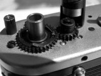
The slow-speed escapement is held by two screws (photo 19), one of which must be accessed
through one of the gears. This should line up if you cock the shutter and set 1/8 sec -
something not easily achieved at this stage! You can turn the largest gear slightly counter-
clockwise (as viewed from above) to achieve the same effect, and hold it there while undoing
the screw. Once the screws are out, lift the mechanism off, carefully manoevering it around
the shutter speed-selector parts. It will unwind too as soon as it's released, don't panic!
Dump the whole mechanism into cleaning fluid and let it soak a while. A small brush will help
to clean it if you have one. Let it dry fully before lubricating. Don't run the mechanism
unlubricated, it's quite delicate and you could damage it this way.
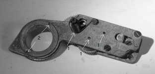
Using a very thin oil, lubricate the points shown (photos 20, points marked "1" & 2). Oil
VERY sparingly, using an oiler or a fine needle to get oil onto the spot required. There are
the six pinion pivots (three on top, three underneath) and the escapement pawl pivot (photo 22),
the wind-ratchet (photo 23) and the spring. Lightly, oil the smaller pinion (gear teeth!) on
each shaft too. Oil the teeth ofthe escapement pawl, again sparingly. Excess oil will only run
somewhere it doesn't belong and attract dirt.
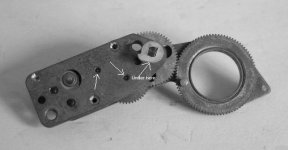
Using a medium grade oil, oil the largest, ring-shaped gear where it runs against the
O-shaped plate (photo 20, points marked "2"). Turn the mechanism upside down and note
the pin on the ring-shaped large gear. Turn this gear clockwise about 3 turns to wind
the mechanism, then release it. See that the mechanism runs smoothly and unwinds compeletely.
It should come to rest in about the same place each time and not stick at any point. Try it
several times, partly to check this and partly to run the new oil around. Once you're happy,
set the mechanism aside somewhere clean (like a zip-loc plastic bag) while the other work
is done.
Now is a good time to deal with the RF/VF, whilst access is easier, then refit the slow-speed
escapement and flash-synchroniser, as detailed below, as the last jobs before refitting the
top cover. It is also a good idea to remove the shutter speed selector and grease the part it
sits on - undo the screw holding it, under which is a spring. Whilst at this stage, oil the
shutter drum shaft pivot: refer to photo 25 or 26, oil sparingly between the top plate and the
selector parts, where the shaft runs through the plate. Also, check the operation of the second
curtain release arm (photo 26A). To remove it, unhook the small spring, noting carefully how it
fits. Withdraw the shaft, clean and lubricate with thin oil then refit it and re-attach the
spring.
Re-fitting the slow-speed mechanism is the reverse of removal, with a couple of complications!
Read on.
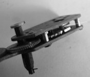
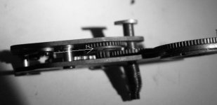
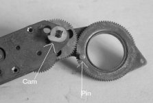
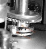
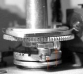
The ring-gear pin (photo 25) is engaged by the speed-selector at slow speeds. The slower the speed
the further it winds the mechanism. The speed-selector sits a little lower on 1/125 or faster,
so it misses the pin for higher speeds. At 1/60 it doesn't quite get to winding anything, but
for 1/15 or less it does. The little cam sticking out underneath the mechanism (photo 24) is what
blocks the shutter closing-curtain (via a tiny lever) until the delay time is up. Photo 25 shows
the shutter cocked at 1/125 with selector (left arrow) missing the pin (right arrow). Photo 26
shows the same situation for 1/2 sec, where the mechanism has been wound some way (same parts
arrowed).
Before re-fitting the mechanism, apply a TINY dab of silicone grease to the cam periphery. Be
aware that the cam operates a tiny lever and must sit beside it, so lower the mechanism
absolutely straight for the last few millimetres to avoid trapping the lever. The cam point
must not sit on top of the lever, hence the mechanism must be held as described below.
Before re-fitting the slow-speed mechanism, set the shutter speed to 1/1000 - do this by lifting
the speed-change and turning clockwise to the last notch. Don't worry about altering the speed
with the shutter un-cocked, at this point it doesn't matter (we'll check later that it's set
properly). Wind the escapement about one and one-half turns by means of the ring-shaped gear,
until the pin is adjacent to the triangular shaped projection. Holding in this position, re-fit
the mechanism, guiding it over the pin sticking up on the speed-change. Still holding the ring-gear,
refit the screws (very fiddly!), moving the gear slightly, if needed, to access the rear screw
that goes through a gear. Now release the mechanism, it should not unwind far. If it unwinds fully,
remove it and find out why! Once refitted Wind the mechanism a little, several times, it should
always unwind back to the exact same point (check the pin position, it should look like photo 25).
Now set the shutter speed to 1/60 by lifting the speed-selector and turning counter-clockwise.
Count your way through the notches to find 1/60. Cock the shutter by turning the film sprocket
in the direction of film travel (this is rough on the fingers!). Do this slowly and watch
the speed machanism as you wind. If anything fouls up, STOP and ascertain why, DON'T continue
to wind! When the shutter is cocked, the speed-selector should ALMOST contact the slow-speed
ring-gear pin. Fire the shutter and repeat with the speed set to 1/15 or less: this time the
pin should be engaged and the mechanism bewound up. Fire again and see if it sounds right.
Refer to photos 25 and 26 again to see how things should look.
Refit the flash-synchroniser once you're happy with the slow-speed escapement.
This part covers removing and servicing the slow-speed mechanism and assumes the top cover
is off.
The mechanism sits over the speed-change mechanism and under the flash-synch switch (photo 17).
The switch is held in place by two screws on diagonal corners. Don't be fooled by the third
foot and hole - no screw there! Lift off the flash-synch switch carefully. While it's off,
clean the contact ring (photo 18) with a fibreglass or fine brass brush if you have one, otherwise
leave it alone. Make sure you return it to its former position if you rotate the moving part.
The slow-speed escapement is held by two screws (photo 19), one of which must be accessed
through one of the gears. This should line up if you cock the shutter and set 1/8 sec -
something not easily achieved at this stage! You can turn the largest gear slightly counter-
clockwise (as viewed from above) to achieve the same effect, and hold it there while undoing
the screw. Once the screws are out, lift the mechanism off, carefully manoevering it around
the shutter speed-selector parts. It will unwind too as soon as it's released, don't panic!
Dump the whole mechanism into cleaning fluid and let it soak a while. A small brush will help
to clean it if you have one. Let it dry fully before lubricating. Don't run the mechanism
unlubricated, it's quite delicate and you could damage it this way.
Using a very thin oil, lubricate the points shown (photos 20, points marked "1" & 2). Oil
VERY sparingly, using an oiler or a fine needle to get oil onto the spot required. There are
the six pinion pivots (three on top, three underneath) and the escapement pawl pivot (photo 22),
the wind-ratchet (photo 23) and the spring. Lightly, oil the smaller pinion (gear teeth!) on
each shaft too. Oil the teeth ofthe escapement pawl, again sparingly. Excess oil will only run
somewhere it doesn't belong and attract dirt.
Using a medium grade oil, oil the largest, ring-shaped gear where it runs against the
O-shaped plate (photo 20, points marked "2"). Turn the mechanism upside down and note
the pin on the ring-shaped large gear. Turn this gear clockwise about 3 turns to wind
the mechanism, then release it. See that the mechanism runs smoothly and unwinds compeletely.
It should come to rest in about the same place each time and not stick at any point. Try it
several times, partly to check this and partly to run the new oil around. Once you're happy,
set the mechanism aside somewhere clean (like a zip-loc plastic bag) while the other work
is done.
Now is a good time to deal with the RF/VF, whilst access is easier, then refit the slow-speed
escapement and flash-synchroniser, as detailed below, as the last jobs before refitting the
top cover. It is also a good idea to remove the shutter speed selector and grease the part it
sits on - undo the screw holding it, under which is a spring. Whilst at this stage, oil the
shutter drum shaft pivot: refer to photo 25 or 26, oil sparingly between the top plate and the
selector parts, where the shaft runs through the plate. Also, check the operation of the second
curtain release arm (photo 26A). To remove it, unhook the small spring, noting carefully how it
fits. Withdraw the shaft, clean and lubricate with thin oil then refit it and re-attach the
spring.
Re-fitting the slow-speed mechanism is the reverse of removal, with a couple of complications!
Read on.
The ring-gear pin (photo 25) is engaged by the speed-selector at slow speeds. The slower the speed
the further it winds the mechanism. The speed-selector sits a little lower on 1/125 or faster,
so it misses the pin for higher speeds. At 1/60 it doesn't quite get to winding anything, but
for 1/15 or less it does. The little cam sticking out underneath the mechanism (photo 24) is what
blocks the shutter closing-curtain (via a tiny lever) until the delay time is up. Photo 25 shows
the shutter cocked at 1/125 with selector (left arrow) missing the pin (right arrow). Photo 26
shows the same situation for 1/2 sec, where the mechanism has been wound some way (same parts
arrowed).
Before re-fitting the mechanism, apply a TINY dab of silicone grease to the cam periphery. Be
aware that the cam operates a tiny lever and must sit beside it, so lower the mechanism
absolutely straight for the last few millimetres to avoid trapping the lever. The cam point
must not sit on top of the lever, hence the mechanism must be held as described below.
Before re-fitting the slow-speed mechanism, set the shutter speed to 1/1000 - do this by lifting
the speed-change and turning clockwise to the last notch. Don't worry about altering the speed
with the shutter un-cocked, at this point it doesn't matter (we'll check later that it's set
properly). Wind the escapement about one and one-half turns by means of the ring-shaped gear,
until the pin is adjacent to the triangular shaped projection. Holding in this position, re-fit
the mechanism, guiding it over the pin sticking up on the speed-change. Still holding the ring-gear,
refit the screws (very fiddly!), moving the gear slightly, if needed, to access the rear screw
that goes through a gear. Now release the mechanism, it should not unwind far. If it unwinds fully,
remove it and find out why! Once refitted Wind the mechanism a little, several times, it should
always unwind back to the exact same point (check the pin position, it should look like photo 25).
Now set the shutter speed to 1/60 by lifting the speed-selector and turning counter-clockwise.
Count your way through the notches to find 1/60. Cock the shutter by turning the film sprocket
in the direction of film travel (this is rough on the fingers!). Do this slowly and watch
the speed machanism as you wind. If anything fouls up, STOP and ascertain why, DON'T continue
to wind! When the shutter is cocked, the speed-selector should ALMOST contact the slow-speed
ring-gear pin. Fire the shutter and repeat with the speed set to 1/15 or less: this time the
pin should be engaged and the mechanism bewound up. Fire again and see if it sounds right.
Refer to photos 25 and 26 again to see how things should look.
Refit the flash-synchroniser once you're happy with the slow-speed escapement.
Last edited:
wolves3012
Mentor
wolves3012
Mentor
wolves3012
Mentor
wolves3012
Mentor
Part 3
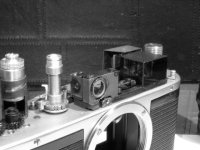
This part covers cleaning and asjusting the rangefinder and viewfinder. It assumes the top
plate has been removed. Access is improved if the flash-synch switch and slow-speed
mechanism have been removed but this is not essential. Photo 27 shows the components.
The VF consists of two main parts: two large prisms glued together and the dioptre correction
lenses. There is little to be done here beyond cleaning the faces of the lenses and the
right-hand side of VF prisms block. Use alcohol on a cotton bud and clean carefully, avoiding
the blackened top and left-hand side of of the VF prism block.
The RF comprises a prism window, the mirror and the operating mechanism. Clean both sides
of the RF prism window (it looks like plain glass but it really is a prism) but take care
NOT to touch the mirror whilst doing so. The mirror is a surface-silvered one, any attempt
at cleaning it will almost certainly damage the silvering. Blow any dust off but otherwise
leave it well alone, don't touch the surface with anything! The pivots for the mechanism
may be oiled sparingly but probably won't need it.
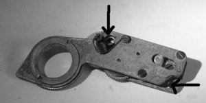
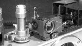
The RF vertical alignment can be adjusted in one of two ways. Refer to photo 28. Normally
the prism (4) is rotated to correct the vertical alignment and the second method should
not be used unless this one fails to move the alignment far enough. If the prism is tight,
soak its periphery with methylated spirits for a while, this will soften the shellac used
to lock it. For the second method, the mirror can be rotated in its mount. There is a
locking screw (1) which must be slackened first. Now use the two screws (2) to rotate the
mirror: slacken one then tighten the other. The screw (3) adjusts the horizontal alignment
and is accessible with the top cover in place. Note that adjusting the prism also has a
small effect on the horizontal alignment, so do the vertical first. Horizontal alignment
is best carried out with the camera fully reassembled. The screw (3) is accessible by
removing the front screw of the top plate just in front of the adjuster. Use it to
adjust the alignment at infinity and rotate the operating cam to adjust at 1m. One
affects the other so it's a case of repeatedly adjusting till you get both right -
it's quite tedious!
This part covers cleaning and asjusting the rangefinder and viewfinder. It assumes the top
plate has been removed. Access is improved if the flash-synch switch and slow-speed
mechanism have been removed but this is not essential. Photo 27 shows the components.
The VF consists of two main parts: two large prisms glued together and the dioptre correction
lenses. There is little to be done here beyond cleaning the faces of the lenses and the
right-hand side of VF prisms block. Use alcohol on a cotton bud and clean carefully, avoiding
the blackened top and left-hand side of of the VF prism block.
The RF comprises a prism window, the mirror and the operating mechanism. Clean both sides
of the RF prism window (it looks like plain glass but it really is a prism) but take care
NOT to touch the mirror whilst doing so. The mirror is a surface-silvered one, any attempt
at cleaning it will almost certainly damage the silvering. Blow any dust off but otherwise
leave it well alone, don't touch the surface with anything! The pivots for the mechanism
may be oiled sparingly but probably won't need it.
The RF vertical alignment can be adjusted in one of two ways. Refer to photo 28. Normally
the prism (4) is rotated to correct the vertical alignment and the second method should
not be used unless this one fails to move the alignment far enough. If the prism is tight,
soak its periphery with methylated spirits for a while, this will soften the shellac used
to lock it. For the second method, the mirror can be rotated in its mount. There is a
locking screw (1) which must be slackened first. Now use the two screws (2) to rotate the
mirror: slacken one then tighten the other. The screw (3) adjusts the horizontal alignment
and is accessible with the top cover in place. Note that adjusting the prism also has a
small effect on the horizontal alignment, so do the vertical first. Horizontal alignment
is best carried out with the camera fully reassembled. The screw (3) is accessible by
removing the front screw of the top plate just in front of the adjuster. Use it to
adjust the alignment at infinity and rotate the operating cam to adjust at 1m. One
affects the other so it's a case of repeatedly adjusting till you get both right -
it's quite tedious!
Attachments
Last edited:
wolves3012
Mentor
Part 4
This part concerns the cleaning and lubrication of the shutter release and re-wind release
mechanisms. It assumes the top cover is removed.
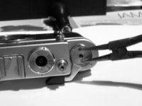
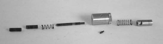
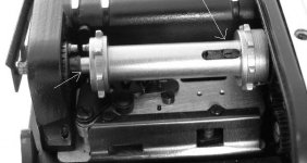
The shutter release/rewind mechanism is held in place by one small set-screw (photo 29).
Before removing this screw, place a finger on the shutter release and keep it there!
Removing the screw without this precaution guarantees the parts will be launched into the
air! Turn the rewind collar about halfway so that the screw is more accessible. Remove the
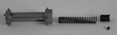
screw then slowly release your finger. Retrieve the parts shown in photo 30 - the shutter
button and spring under it, the rewind collar, the shutter rod with 2 collars and a spring
around them. It's quite likely that this lot will be well gunged up and the lower collar
may not come out. If so, don't worry too much about it but beware of it falling out and
becoming lost. Dump the lot into cleaning fluid for a while. While it's soaking, clean
inside the tube where it all fits, using a cotton bud or similar, soaked in cleaning fluid.
This will also clean the gear intruding into the bottom of the tube. Lubricate the gear along
with the one it meshes with; use silicone grease.
Lubricate the cleaned parts with silicone grease and reassemble. Take care that the shutter
release rod is inserted the right way up - the narrowed part goes at the TOP. Make sure the
rod enters the shutter button properly, a little wiggling as you put the button back in may
be needed. Line up the L-shaped cut-out in the shutter button with the hole in the rewind
collar and replace the screw, hold the button down partway as you replace the screw. Make
sure the button and rewind collar operate properly. It's very easy to mis-align the cut-out
so that the screw locks the shutter button solid - you may need several attempts!
The rewind collar disengages a dog-clutch inside the film sprocket when in the rewind
position. Look at the sprocket and you will see a slot near the top (photo 31) with a screw
showing (don't be tempted to undo the screw, nor the one in the top of the sprocket). If the
sprocket fails to engage properly after rewinding films, this is the likely culprit. A few
drops of cleaning fluid dropped into the slot will probably free things. Put a drop of oil
here regardless. Note that cleaning fluid added will find its way out of the bottom of the
sprocket, so wrap some tissue around it to prevent it running where it's not wanted. The
shaft at the bottom of the sprocket should have a small drop of oil too, turn the rewind
collar fully clockwise first to make access easier.
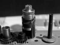
If the rewind still sticks after this, the top plate must be removed to get at the dog-clutch.
This entails major disassembly and is not covered in this "how to". The clutch and sprocket
internals are shown in photo 32, for those interested.
While you're in that area of the camera, clean and lubricate the gears found by the top of
sprocket - use silicone grease. Be careful not to damage or displace the ratchet or its
spring, located between the spool and sprocket gears. This task is easier if the spool is
removed, as it will be if the top plate has been removed. Alternatively undo the large
screw head found in the base of the spool and remove the shaft, spring and spool. Note the
plastic part in the top of the spool, like a washer with "ears". Replace carefully to ensure
this part sits properly in the top of the spool - it's a royal pain!
This part concerns the cleaning and lubrication of the shutter release and re-wind release
mechanisms. It assumes the top cover is removed.
The shutter release/rewind mechanism is held in place by one small set-screw (photo 29).
Before removing this screw, place a finger on the shutter release and keep it there!
Removing the screw without this precaution guarantees the parts will be launched into the
air! Turn the rewind collar about halfway so that the screw is more accessible. Remove the
screw then slowly release your finger. Retrieve the parts shown in photo 30 - the shutter
button and spring under it, the rewind collar, the shutter rod with 2 collars and a spring
around them. It's quite likely that this lot will be well gunged up and the lower collar
may not come out. If so, don't worry too much about it but beware of it falling out and
becoming lost. Dump the lot into cleaning fluid for a while. While it's soaking, clean
inside the tube where it all fits, using a cotton bud or similar, soaked in cleaning fluid.
This will also clean the gear intruding into the bottom of the tube. Lubricate the gear along
with the one it meshes with; use silicone grease.
Lubricate the cleaned parts with silicone grease and reassemble. Take care that the shutter
release rod is inserted the right way up - the narrowed part goes at the TOP. Make sure the
rod enters the shutter button properly, a little wiggling as you put the button back in may
be needed. Line up the L-shaped cut-out in the shutter button with the hole in the rewind
collar and replace the screw, hold the button down partway as you replace the screw. Make
sure the button and rewind collar operate properly. It's very easy to mis-align the cut-out
so that the screw locks the shutter button solid - you may need several attempts!
The rewind collar disengages a dog-clutch inside the film sprocket when in the rewind
position. Look at the sprocket and you will see a slot near the top (photo 31) with a screw
showing (don't be tempted to undo the screw, nor the one in the top of the sprocket). If the
sprocket fails to engage properly after rewinding films, this is the likely culprit. A few
drops of cleaning fluid dropped into the slot will probably free things. Put a drop of oil
here regardless. Note that cleaning fluid added will find its way out of the bottom of the
sprocket, so wrap some tissue around it to prevent it running where it's not wanted. The
shaft at the bottom of the sprocket should have a small drop of oil too, turn the rewind
collar fully clockwise first to make access easier.
If the rewind still sticks after this, the top plate must be removed to get at the dog-clutch.
This entails major disassembly and is not covered in this "how to". The clutch and sprocket
internals are shown in photo 32, for those interested.
While you're in that area of the camera, clean and lubricate the gears found by the top of
sprocket - use silicone grease. Be careful not to damage or displace the ratchet or its
spring, located between the spool and sprocket gears. This task is easier if the spool is
removed, as it will be if the top plate has been removed. Alternatively undo the large
screw head found in the base of the spool and remove the shaft, spring and spool. Note the
plastic part in the top of the spool, like a washer with "ears". Replace carefully to ensure
this part sits properly in the top of the spool - it's a royal pain!
Attachments
wolves3012
Mentor
Part 5
This part covers lubricating cleaning the shutter mechanisms. The top cover must have been removed.
There are two areas that require lubrication. The bearings for the shutter spring rollers and drum
need to be lubricated at several points from the top and bottom. If these appear to be seriously
gummed up then the top plate will need to be removed, which means the whole shutter crate will need
to be disassembled, a major task. Fortunately, this probably not be needed. The restrictor gear is only
accessible from the bottom.
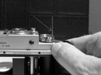
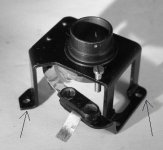
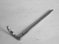
To access these parts, the restrictor gear in particular, the crate must be removed from the body as
follows: Remove the three rear top plate screws (photo 33) and two front screws (photo 34). Remove the
self-timer arm by undoing the retaining screw with sharp-nosed pliers or tweezers (photo 35) in the
two holes (NOTE: LEFT-HAND thread so unscrew clockwise). Recover the plastic sleeve behind the arm
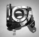
and the washer-like light-seal (photo 36) . Remove the four lens-mount screws (photo 37) and the mount
(photo 38). Note the shims under the mount (photo 39) and the orientation of the mount. The mount
and shims must be replaced EXACTLY as you found them or the lens-register will be incorrect. Remove
the two crate retaining screws (photo 40).
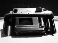
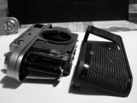
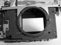
Now the body can be removed. First, pry the lower part forwards (photo 41) and separate the body
completely (photo 42). Note that there is a light-seal of black string glued around the lower part
of the mount area, this tends to stick the two parts together. Break the bond gently and try not to
disturb the string. Glue it back or replace it if it comes adrift.
The restrictor gears sit in the lower, front, right-hand corner and can bee seen in photos 43 and 44
at the lower left. To access them properly, along with the roller pivots, remove the crate front as
follows: First, undo the four baffle screws (photo 43). The baffles will fall into the crate but
they have so little room that replacing the screws later is not difficult. Take care that they do not
move and cut into the shutter cloth parts. Now remove the four crate front screws (photo 44) and the
crate front. Carefully recover the baffles, noting how they fitted.
Clean the restrictor gears (photo 45) as needed and lubricate them with silicone grease. The shutter
will need to be cocked and fired to rotate these gears - depending on the stage of disassembly you
can turn the film sprocket to cock it (turn in film-travel direction!).
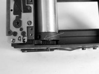
Lubricate the spring rollers sparingly, with the camera upside-down (photo 46) using a medium oil.
Make sure the oil goes between the moving parts - the thinner part of the roller is fixed. Cameras
that make a high-pitched zzzzzzzzzp sound when fired usually do so because these points are dry.
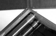
One final point to oil here is the shutter drum shaft. This can be accessed just above the shutter
curtain but GREAT CARE is required not to get oil on the curtain or damage it. If in doubt, leave
this part. You will need a very fine-tipped precision lubricator or hypodermic to get oil where
required. Photos 47 and 48 show the drum without the curtains in place. As can be seen, there is one
access blocked by a pin (photo 47), the other is not (photo 48) and can be used. The shutter must
be partially cocked to get this in position, and curtain damage is a risk when passing the oiler
over its edge. Use very little of a thin oil here.
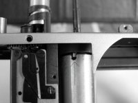
Photo 49 shows the location of the bottom drum shaft pivot, which should also be lightly oiled. It
can be accessed by removing the lower spring cover (photo 50). Note the spacers under the cover,
they are not identical, fit as per the photo. Remove the shutter latch (the silver disc in the photo)
after noting its orientation. Be sure the screw holding it is TIGHT when replacing. Lubricate the
contact surfaces of the latch with silcone grease.
Photo 51 shows the upper roller pivots. These can only be oiled by removing the whole VF/RF
assembly from the top of the camera, a rather fiddly process.
This part covers lubricating cleaning the shutter mechanisms. The top cover must have been removed.
There are two areas that require lubrication. The bearings for the shutter spring rollers and drum
need to be lubricated at several points from the top and bottom. If these appear to be seriously
gummed up then the top plate will need to be removed, which means the whole shutter crate will need
to be disassembled, a major task. Fortunately, this probably not be needed. The restrictor gear is only
accessible from the bottom.
To access these parts, the restrictor gear in particular, the crate must be removed from the body as
follows: Remove the three rear top plate screws (photo 33) and two front screws (photo 34). Remove the
self-timer arm by undoing the retaining screw with sharp-nosed pliers or tweezers (photo 35) in the
two holes (NOTE: LEFT-HAND thread so unscrew clockwise). Recover the plastic sleeve behind the arm
and the washer-like light-seal (photo 36) . Remove the four lens-mount screws (photo 37) and the mount
(photo 38). Note the shims under the mount (photo 39) and the orientation of the mount. The mount
and shims must be replaced EXACTLY as you found them or the lens-register will be incorrect. Remove
the two crate retaining screws (photo 40).
Now the body can be removed. First, pry the lower part forwards (photo 41) and separate the body
completely (photo 42). Note that there is a light-seal of black string glued around the lower part
of the mount area, this tends to stick the two parts together. Break the bond gently and try not to
disturb the string. Glue it back or replace it if it comes adrift.
The restrictor gears sit in the lower, front, right-hand corner and can bee seen in photos 43 and 44
at the lower left. To access them properly, along with the roller pivots, remove the crate front as
follows: First, undo the four baffle screws (photo 43). The baffles will fall into the crate but
they have so little room that replacing the screws later is not difficult. Take care that they do not
move and cut into the shutter cloth parts. Now remove the four crate front screws (photo 44) and the
crate front. Carefully recover the baffles, noting how they fitted.
Clean the restrictor gears (photo 45) as needed and lubricate them with silicone grease. The shutter
will need to be cocked and fired to rotate these gears - depending on the stage of disassembly you
can turn the film sprocket to cock it (turn in film-travel direction!).
Lubricate the spring rollers sparingly, with the camera upside-down (photo 46) using a medium oil.
Make sure the oil goes between the moving parts - the thinner part of the roller is fixed. Cameras
that make a high-pitched zzzzzzzzzp sound when fired usually do so because these points are dry.
One final point to oil here is the shutter drum shaft. This can be accessed just above the shutter
curtain but GREAT CARE is required not to get oil on the curtain or damage it. If in doubt, leave
this part. You will need a very fine-tipped precision lubricator or hypodermic to get oil where
required. Photos 47 and 48 show the drum without the curtains in place. As can be seen, there is one
access blocked by a pin (photo 47), the other is not (photo 48) and can be used. The shutter must
be partially cocked to get this in position, and curtain damage is a risk when passing the oiler
over its edge. Use very little of a thin oil here.
Photo 49 shows the location of the bottom drum shaft pivot, which should also be lightly oiled. It
can be accessed by removing the lower spring cover (photo 50). Note the spacers under the cover,
they are not identical, fit as per the photo. Remove the shutter latch (the silver disc in the photo)
after noting its orientation. Be sure the screw holding it is TIGHT when replacing. Lubricate the
contact surfaces of the latch with silcone grease.
Photo 51 shows the upper roller pivots. These can only be oiled by removing the whole VF/RF
assembly from the top of the camera, a rather fiddly process.
wolves3012
Mentor
wolves3012
Mentor
wolves3012
Mentor

wolves3012
Mentor
rolleistef
Well-known
Ahh thank you so much mate! There was nowhere I could find such instructions for my z4 CLA, and I reckon there is so much grease that the 30th don't work correctly unless the camera is correctly warmed before use!
wolves3012
Mentor
That's all folks! No, I didn't cover removing/replacing curtains or re-tensioning them - I didn't need to on this camera and there are web pages covering this aspect already. Re-assembly, as in all the best manuals, is the reverse of disassembly - read the sections again to be aware of any noted precautions though.
Comments or corrections are welcomed, as are easier methods for some of the jobs shown!
Maybe a mod could make this sticky please, if you think it's appropriate?
Comments or corrections are welcomed, as are easier methods for some of the jobs shown!
Maybe a mod could make this sticky please, if you think it's appropriate?
rolleistef
Well-known
yes, definitely!
Share:
-
This site uses cookies to help personalise content, tailor your experience and to keep you logged in if you register.
By continuing to use this site, you are consenting to our use of cookies.